How To Create A Flow Cytometry Quality Assurance Protocol For Your Lab

Editor’s note: This is based on Edita’s experiences implementing the proposals reported in Perfetto et al., (2012) Nature Protocols 7:2067. She submitted this to the ExCyte Mastery Class and developed the Excel sheet (attached) to assist others in tracking their QC data.
Developing and implementing a new Quality Control (QC) protocol can sometimes be a daunting task.
With the continued emphasis on reproducibility in science, QC programs are an essential step that cytometrists are encouraged to both develop and implement.
This QC program comprises several assays that are focused on three important characteristics of the flow cytometer:
(1) Optimal instrument setting (e.g. instrument optimization)
(2) Cytometer sensitivity (e.g. instrument calibration)
(3) Monitoring of day-to-day variability in measurement (e.g. quality assurance)
QC Program Step #1 — Instrument Optimization
Instrument optimization assays include protocols useful for determination of laser power, photoelectron efficiency, testing of filter characteristics, evaluation of signal synchronization, and laser delay determination.
These are central characteristics of the flow cytometer and understanding these values at installation help ensure that when changes are made, the system is performing as well as when it was first brought into service.
In addition to making these measurements at installation, instruments should also be optimized whenever the optical pathways are changed, including: changing a filter installation, installation of a new laser, and/or realignment because of a new flow cell. Basically, whenever an optical pathway is changed. This gives the user a baseline to know how the instrument is performing and a reference for when there are issues.
Instrument optimizations do require some specialized equipment, namely a laser power meter and super-reflecting mirror to perform any of these tests.
QC Program Step #2 — Cytometer Calibration
There are two separate protocols necessary for cytometer calibration:
- Determining the sensitivity of PMTs
- Validation of PMT sensitivity
To complete the first protocol, three bead sets are needed. For this work, you should use:
- Single peak beads – BC Flow-Set Pro Fluorospheres
- Multipeak beads – DakoFluorospheres
- Unstained beads – DakoFluorospheres
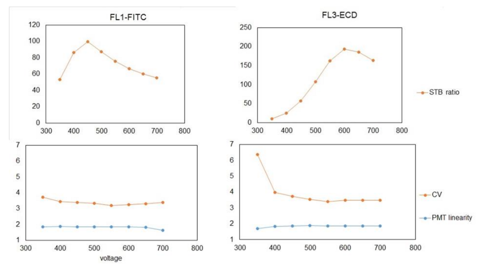
To generate the top graphs in the below figure, the voltage was plotted against the Signal-to-Background (S-T-B). This is calculated by dividing the median fluorescent intensity (MFI) of a well-separated peak by the background MFI. In this case, I chose the 4th peak, as it was nicely displayed and recognized throughout most of voltage range and on most detectors.

These data also allow for the determination of PMT linearity, which is measured as difference between MFIs of two adjacent peaks from multiple-peak beads divided by MFI of lower peak from selected peak pair. Like the PMT calibration, this value is plotted over the voltage range.
To interpret the top graphs in the above figure, you need to determine the voltage with the highest S-T-B. As shown above, the FL1 detector (BP525/30) is most sensitive at 450 V, whereas the FL3 detector (BP620/30) is most sensitive at 600 V. Equipped with this information, when you run a new experiment, you should use the voltage with the highest S-T-B ratio for primary detector as your default voltage.
The PMT linearity showed that the FL1 detector gives linear response throughout the tested voltage range, while in the case of FL3 the lower voltage (below 450V) setting should be avoided because the response to the fluorescence intensity is not linear.
Remember that compensation cannot be correctly calculated if the signal is not in the linear range of the PMT.
Validation of the PMT voltages is performed to confirm the results of the optimization step above. The protocol for this requires particles (CompBeads) that give a single peak when stained with antibodies. For this experiment, three antibodies were chosen that had been previously characterized (titrated) to ensure the optimal signal.
Here, polystyrene microparticles were used, which bind any mouse kappa light chain-bearing immunoglobulin, as well as three fluorochrome labeled antibodies (mouse CD16-PC5, CD45-PC7 and CD36-FITC), which are suitable for three different detectors. The titration curve showed that the CompBeads can be stained in ratio 1:20, 1:20 and 1:5 for CD16-PC5, CD45-PC7 and CD36-FITC, respectively.

As a second step, CompBeads were mixed with a negative control (without any binding capacity) and labeled individually with an appropriate marker. Finally, the primary detector (FL4 for PC5, FL5 for PC7 and FL1 for FITC) was set to gain highest fluorescence response (see below).
The highest fluorescence for primary detectors was determined as 670 V at FL4 (for CD16-PC5), 500 V at FL5 (for CD45-FL5) and 500 V at FL1 (for CD36-FITC).

The next step was to set the secondary channels to a minimal MFI. For this, a wide range of detector voltages (400-700 V) were tested. The voltage with the lowest MFI found in PMT linear region was chosen (see below).
As you can see in the above graphs, decreasing MFI values were found on the primary channels (yellow bars), despite being set on a single voltage during the course of all measurements.
Notice how drastically the setting of secondary channels can influence results on primary channels.
When calibrating your cytometer, the final step is to measure rainbow single-peak beads using the same primary/secondary channel settings that were used for your individual fluorochrome.

The repeated measurements (n=20) serves for determination of the target value range for CV, which is the highest value found within +- 1 SD or +- 10 % of mean value.
In the above figure you can see that the FL5 detector has the lowest sensitivity in comparison to the other detectors, particularly when compared to the FL1 detector. Even if FL5 detector is set to achieve the highest MFI, its response is much lower than the response achieved by the FL1 detector.
QC Program Step #3 – Implement QC Checkpoints
After spending the time and effort to perform the above measurements to optimize your instrument, it’s important to implement and monitor how the system is changing over time.
Implementing the proper Quality Assurance (QA) checkpoints is the only way ensure that your flow cytometer is functioning properly over time. It’s also the only way to determine what the issue is and how to fix it if there are deviations in these checkpoints.
To implement these QA checkpoints, data from three different bead sets must be recorded and analyzed. The beads include:
- Single peak bead
- Multiple peak bead
- Unstained bead
The parameters to be monitored or “checked” include:
- PMT voltage
- CV of the single peak bead
- MFI of a defined peak (peak 4)
- MFI of the unstained beads
Altogether, this allows for three calculations that can be used to assess the overall quality of the instrument over time. These calculations are:
- Accuracy (voltage setting as a function of time)
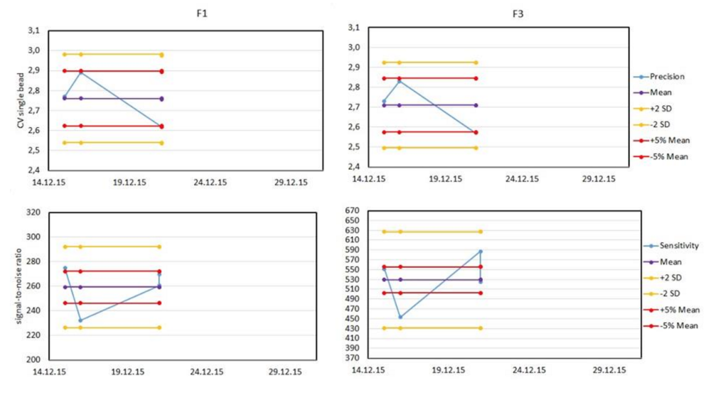
- Precision (CV as a function of time)
- Sensitivity (S-T-B ratio as a function of time)
Once the above data are collected, they must be plotted for analysis. The most common plot is the Levey-Jennings plot, which shows the daily data, a running average and lines representing tolerance ranges.

These plots are commonly defined relative on the stringency needs of the investigator to either +/- 2 standard deviations from the mean, or +/- 5% of the mean value. Typical plots are shown below.
If your instrument does not perform this analysis automatically, or if you’re interested in having a second QA protocol that is independent from your vendor’s protocol, you can download this QA protocol spreadsheet and use it to monitor your data over time.
The above QA protocol spreadsheet has been developed for a FC500 instrument, but the logic can be applied to any number of detectors for any system.
The spreadsheet is organized as follows:
- Tab 1: Quality control data – this is the place to put the data that will be the basis of the calculations. Make sure to include the bead type and LOT number. This is especially critical when there is a change to the bead lot. When coming to the end of a lot of beads, it is good to order the new lot and perform an overlap experiment where the old and new lots of beads are run in parallel and any changes to target values can be identified and noted.
- Tab 2: Accuracy – here the data is used to calculate the change in voltage over time.
- Tab 3: Precision – here the coefficient of variation (CV) is calculated using a single bead over time.
- Tab 4: Sensitivity – here the changes in S-T-B are calculated over time.
By adding your data to the first tab, all the graphs and tables will be updated, allowing for a rapid check and confirmation that your instrument is performing within acceptable ranges. A Levey-Jennings plot for detector is shown with both the +/-2 SD and +/-5% of the mean for each value. This helps you visualize the changes over time, and identify trends before they become problems.
Implementing a system of quality assurance protocols of this nature lends confidence to the data collected, especially for those researchers performing longitudinal studies. Optimal instrument setting, cytometer sensitivity, and monitoring of day-to-day variability in measurement leads to improved assurance for those using this instrument to collect their critical data. QC programs will continue to be prudent measures for cytometrists to take as they align with the current emphasis on quality and reproducibility.

ABOUT TIM BUSHNELL, PHD
Tim Bushnell holds a PhD in Biology from the Rensselaer Polytechnic Institute. He is a co-founder of—and didactic mind behind—ExCyte, the world’s leading flow cytometry training company, which organization boasts a veritable library of in-the-lab resources on sequencing, microscopy, and related topics in the life sciences.
More Written by Tim Bushnell, PhD


